Using Home Assistant with IR controlled devices

When my stereo amplifier stopped working I could’ve bought a new one but after a quick look inside I was pretty sure the damage was minor so I brought it to a repair service. When I could pick it up again not only were the costs way below the price of a new amplifier but the repair service basically did a full recap with good quality capacitors so not only will it last another decade or two it also still sounds great.

But since this is a pre smart era device it only came with a bulky IR remote, so no possibility to control it via Wi-Fi. I bought a cheap Wi-Fi remote control device that could be flashed with Tasmota and integrated it with my Domoticz setup. Then we got a new thermostat that worked with Domoticz initially but after a firmware update it stopped working. With Home Assistant everything worked except for the IR remote control so for a while I used both solutions.

Not ideal so I dug a bit deeper to get the IR remote control to work with Home Assistant. Since user stories on this matter are pretty much non-existent here are the steps to get a similar solution going on your Home Assistant setup. Be warned that this is not a step-by-step walkthrough, I’m assuming you know how to flash ESP devices, that you know your way around Home Assistant and Tasmota and that you have your own MQTT server running.

First you will have to acquire a Wi-Fi remote control device that can be flashed with Tasmota. I got one from Amazon similar to this unit. Flashed it over the air with tuya-convert. Next step was to add the Pyscript HACS integration to Home Assistant. Then I added the following Python script wich I named irsend.py to the pyscripts directory.

#!/usr/bin/env python3

import paho.mqtt.client as mqtt

mqtt_server = "localhost"
topic = "ir_remote01"

# IR codes
ir_codes = {}
ir_codes['stereo_protocol'] = 'NEC'
ir_codes['stereo_volume_down'] = '0xE13E31CE'
ir_codes['stereo_volume_up'] = '0xE13E11EE'
ir_codes['stereo_off'] = '0xE13E13EC'
ir_codes['stereo_on'] = '0xE13EA45B'
ir_codes['stereo_tuner'] = '0xE13EBB44'
ir_codes['stereo_aux'] = '0xE13ED926'
ir_codes['stereo_cd'] = '0xE13EA15E'
ir_codes['stereo_video'] = '0xE13E43BC'


@service
def send_ir_code(action=None, id=None):
    log.info(f'irsend: got action {action} id {id}')
    ir_protocol = ir_codes[f'{id}_protocol']
    ir_code = ir_codes[f'{id}_{action}']
    ir_payload = f'{{"Protocol":"{ir_protocol}","Bits":32,"Data":"{ir_code}"}}'
    log.info(f'irsend: sending payload {ir_payload}')
    mqtt_client = mqtt.Client()
    mqtt_client.connect(mqtt_server)
    mqtt_publish = mqtt_client.publish(f'{topic}/cmnd/irsend', ir_payload)
    mqtt_client.disconnect()

What this script does is sending a message over MQTT to the IR remote control, the IR remote control then converts this message to an IR signal and transmits this signal. The script needs two input parameters, action and id. These parameters are made available to the script through pyscript. The Python @service decorator makes the script available as a Service in Home Assistant.

With this Service working I can add it to a View. I used a Grid card for this and added Buttons cards to this Grid.

The Grid Card Configuration looks like this.

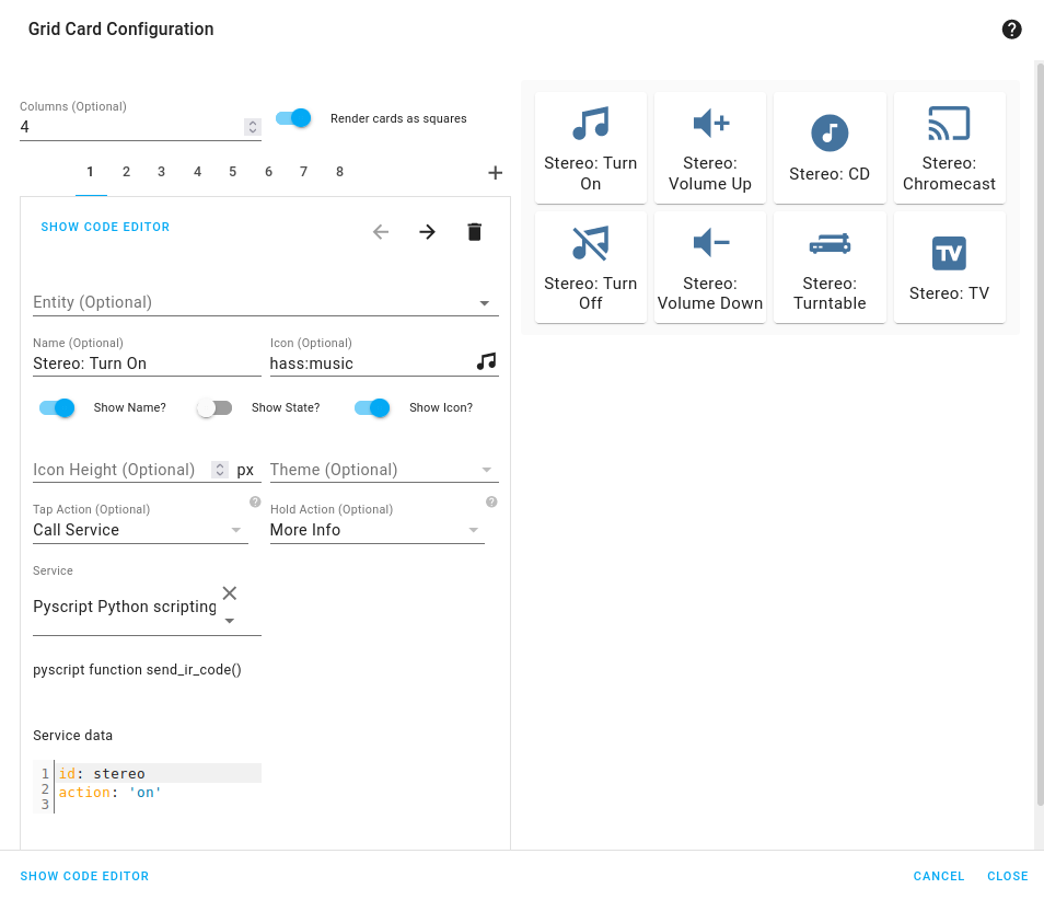
Added a Name, an Icon and set the Tap Action to Call Service. As a Service I could select Pyscript Python scripting: send_ir_code and as Service data I entered an id and an action as a dictionary, so {id: stereo, action: on}. Did this for all the other actions and now I can control my pre smart age stereo in a smart way.

Using Home Assistant with IR controlled devices

RPi 3 and the real time kernel

As a beta tester for MOD I thought it would be cool to play around with netJACK which is supported on the MOD Duo. The MOD Duo can run as a JACK master and you can connect any JACK slave to it as long as it runs a recent version of JACK2. This opens a plethora of possibilities of course. I’m thinking about building a kind of sidecar device to offload some stuff to using netJACK, think of synths like ZynAddSubFX or other CPU greedy plugins like fat1.lv2. But more on that in a later blog post.

So first I need to set up a sidecar device and I sacrificed one of my RPi’s for that, an RPi 3. Flashed an SD card with Raspbian Jessie Lite and started to do some research on the status of real time kernels and the Raspberry Pi because I’d like to use a real time kernel to get sub 5ms system latency. I compiled real time kernels for the RPi before but you had to jump through some hoops to get those running so I hoped things would have improved somewhat. Well, that’s not the case so after having compiled a first real time kernel the RPi froze as soon as I tried to runapt-get install rt-tests. After having applied a patch to fix how the RPi folks implemented the FIQ system the kernel compiled without issues:

Linux raspberrypi 4.9.33-rt23-v7+ #2 SMP PREEMPT RT Sun Jun 25 09:45:58 CEST 2017 armv7l GNU/Linux

And the RPi seems to run stable with acceptable latencies:

Histogram of the latency on the RPi with a real time kernel during 300000 cyclictest loops

So that’s a maximum latency of 75 µs, not bad. I also spotted some higher values around 100 but that’s still okay for this project. The histogram was created with mklatencyplot.bash. I used a different invocation of cyclictest though:

cyclictest -Sm -p 80 -n -i 500 -l 300000

And I ran hackbench in the background to create some load on the RPi:

(while true; do hackbench > /dev/null; done) &

Compiling a real time kernel for the RPi is still not a trivial thing to do and it doesn’t help that the few howto’s on the interwebs are mostly copy-paste work, incomplete and contain routines that are unclear or even unnecessary. One thing that struck me too is that the howto’s about building kernels for RPi’s running Raspbian don’t mention the make deb-pkg routine to build a real time kernel. This will create deb packages that are just so much easier to transfer and install then rsync’ing the kernel image and modules. Let’s break down how I built a real time kernel for the RPi 3.

First you’ll need to git clone the Raspberry Pi kernel repository:

git clone -b 'rpi-4.9.y' --depth 1 https://github.com/raspberrypi/linux.git

This will only clone the rpi-4.9.y branch into a directory called linux without any history so you’re not pulling in hundreds of megs of data. You will also need to clone the tools repository which contains the compiler we need to build a kernel for the Raspberry Pi:

git clone https://github.com/raspberrypi/tools.git

This will end up in the tools directory. Next step is setting some environment variables so subsequent make commands pick those up:

export KERNEL=kernel7
export ARCH=arm
export CROSS_COMPILE=/path/to/tools/arm-bcm2708/gcc-linaro-arm-linux-gnueabihf-raspbian/bin/arm-linux-gnueabihf-
export CONCURRENCY_LEVEL=$(nproc)

The KERNEL variable is needed to create the initial kernel config. The ARCH variable is to indicate which architecture should be used. The CROSS_COMPILE variable indicates where the compiler can be found. The CONCURRENCY_LEVEL variable is set to the number of cores to speed up certain make routines like cleaning up or installing the modules (not the number of jobs, that is done with the -j option of make).

Now that the environment variables are set we can create the initial kernel config:

cd linux
make bcm2709_defconfig

This will create a .config inside the linux directory that holds the initial kernel configuration. Now download the real time patch set and apply it:

cd ..
wget https://www.kernel.org/pub/linux/kernel/projects/rt/4.9/patch-4.9.33-rt23.patch.xz
cd linux
xzcat ../patch-4.9.33-rt23.patch.xz | patch -p1

Most howto’s now continue with building the kernel but that will result in a kernel that will freeze your RPi because of the FIQ system implementation that causes lock ups of the RPi when using threaded interrupts which is the case with real time kernels. That part needs to be patched so download the patch and dry-run it:

cd ..
wget https://www.osadl.org/monitoring/patches/rbs3s/usb-dwc_otg-fix-system-lockup-when-interrupts-are-threaded.patch
cd linux
patch -i ../usb-dwc_otg-fix-system-lockup-when-interrupts-are-threaded.patch -p1 --dry-run

You will notice one hunk will fail, you will have to add that stanza manually so note which hunk it is for which file and at which line it should be added. Now apply the patch:

patch -i ../usb-dwc_otg-fix-system-lockup-when-interrupts-are-threaded.patch -p1

And add the failed hunk manually with your favorite editor. With the FIQ patch in place we’re almost set for compiling the kernel but before we can move on to that step we need to modify the kernel configuration to enable the real time patch set. I prefer doing that with make menuconfig. You will need the libncurses5-dev package to run this commando so install that with apt-get install libncurses5-dev. Then select Kernel Features - Preemption Model - Fully Preemptible Kernel (RT) and select Exit twice. If you’re asked if you want to save your config then confirm. In the Kernel features menu you could also set the the timer frequency to 1000 Hz if you wish, apparently this could improve USB throughput on the RPi (unconfirmed, needs reference). For real time audio and MIDI this setting is irrelevant nowadays though as almost all audio and MIDI applications use the hr-timer module which has a way higher resolution.

With our configuration saved we can start compiling. Clean up first, then disable some debugging options which could cause some overhead, compile the kernel and finally create ready to install deb packages:

make clean
scripts/config --disable DEBUG_INFO
make -j$(nproc) deb-pkg

Sit back, enjoy a cuppa and when building has finished without errors deb packages should be created in the directory above the linux one. Copy the deb packages to your RPi and install them on the RPi with dpkg -i. Open up /boot/config.txt and add the following line to it:

kernel=vmlinuz-4.9.33-rt23-v7+

Now reboot your RPi and it should boot with the realtime kernel. You can check with uname -a:

Linux raspberrypi 4.9.33-rt23-v7+ #2 SMP PREEMPT RT Sun Jun 25 09:45:58 CEST 2017 armv7l GNU/Linux

Since Rasbian uses almost the same kernel source as the one we just built it is not necessary to copy any dtb files. Also running mkknlimg is not necessary anymore, the RPi boot process can handle vmlinuz files just fine.

The basis of the sidecar unit is now done. Next up is tweaking the OS and setting up netJACK.

Edit: there’s a thread on LinuxMusicians referring to this article which already contains some very useful additional information.

RPi 3 and the real time kernel

Using the Tascam US-144MKII with Linux

Today I got a Tascam US-144MKII from a colleague because he couldn’t use it anymore with Mac OSX. Apparently this USB2.0 audio interface stopped working on El Capitan. Tascam claims they’re working on a driver but they’re only generating bad publicity with that announcement it seems. So he gave it to me, maybe it would work on Linux.

Tascam US-144MKII
Tascam US-144MKII

First thing I did was plugging it in. The snd_usb_122l module got loaded but that was about it. So much for plug and play. There are reports though that this interface should work so when I got home I started digging a bit deeper. Apparently you have to disable the ehci_hcd USB driver, which is actually the USB2.0 controller driver, and force the US-144MKII to use the uhci_hcd USB1.1 driver instead so that it thinks it’s in USB1.1 mode. This limits the capabilities of the device but my goal for today was to get sound out of this interface, not getting the most out of it.

I quickly found out that on my trusty XPS13 forcing USB1.1 was probably not going to work because it only has USB3.0 ports. So I can disable the ehci_hcd driver but then it seems the xhci_hcd USB3.0 driver takes over. And disabling that driver effectively disables all USB ports. So I grabbed an older notebook with USB2.0 ports and disabled the ehci_hcd driver by unbinding it since it’s not compiled as a module. Unbinding a driver is done by writing the system ID of a device to a so-called unbind file of the driver that is bound to this device. In this case we’re interested in the system ID’s of the devices that use the ehci_hcd driver which can be found in /sys/bus/drivers/ehci-pci/:

# ls /sys/bus/pci/drivers/ehci-pci/
0000:00:1a.7  bind  new_id  remove_id  uevent  unbind
# echo -n "0000:00:1a.7" > /sys/bus/pci/drivers/ehci-pci/unbind

This will unbind the ehci_hcd driver from the device with system ID 0000:00:1a.7 which in this case is an USB2.0 controller.When plugging in the USB interface it now got properly picked up by the system and I was greeted with an active green USB led on the interface as proof.

$ cat /proc/asound/cards
 0 [Intel          ]: HDA-Intel - HDA Intel
                      HDA Intel at 0xf4800000 irq 46
 1 [US122L         ]: USB US-122L - TASCAM US-122L
                      TASCAM US-122L (644:8020 if 0 at 006/002

So ALSA picked it up as a device but it doesn’t show up in the list of sound cards when issuing aplay -l. This is because you have to tell ALSA to talk to the device in a different way then to a normal audio interface. Normally an audio interface can be addressed by using the hw plugin which is the most low-level ALSA plugin that does nothing more than talking to the driver and this is what most applications use, including JACK. The US-144MKII works differently though, its driver snd_usb_122l has to be accessed with the use of the usb_stream plugin which is part of the libasound2-plugins package and that allows you to set a PCM device name that can be used with JACK for instance. This can be done with the following .asoundrc file that you have to create in the root of your home directory:

pcm.us-144mkii {
        type usb_stream
        card "US122L"
}

ctl.us-144mkii {
        type hw
        card "US122L"
}

What we do here is creating a PCM device called us-144mkii and coupling that to the card name we got from cat /proc/asound/cards which is US122L. Of course you can name the PCM device anything you want. Almost all other examples name it usb_stream but that’s a bit confusing because that is the name of the plugin and you’d rather have a name that has some relation to the device you’re using. Also practically all examples use card numbers. But who says that the USB audio interface will always be card 0, or 1. It could also be 2, or 10 if you have 9 other audio interfaces. Other examples work around this by fixing the order of the numbers that get assigned to each available audio interface by adjusting the index parameter for the snd_usb_122l driver. But why do that when ALSA also accepts the name of the card? This also makes thing a lot easier to read, it’s now clear that we are coupling the PCM name us-144mkii to the card named US122L. And we’re avoiding having to edit system-wide settings. The ctl stanza is not strictly necessary but it prevents the following warning when starting JACK:

ALSA lib control.c:953:(snd_ctl_open_noupdate) Invalid CTL us-144mkii
control open "us-144mkii" (No such file or directory)

So with the .asoundrc in place you can try starting JACK:

$ jackd -P85 -t2000 -dalsa -r48000 -p512 -n2 -Cus-144mkii -Pus-144mkii
jackd 0.124.2
Copyright 2001-2009 Paul Davis, Stephane Letz, Jack O'Quinn, Torben Hohn and others.
jackd comes with ABSOLUTELY NO WARRANTY
This is free software, and you are welcome to redistribute it
under certain conditions; see the file COPYING for details

no message buffer overruns
JACK compiled with System V SHM support.
loading driver ..
apparent rate = 48000
creating alsa driver ... us-144mkii|us-144mkii|512|2|48000|0|0|nomon|swmeter|-|32bit
configuring for 48000Hz, period = 512 frames (10.7 ms), buffer = 2 periods
ALSA: final selected sample format for capture: 24bit little-endian in 3bytes format
ALSA: use 2 periods for capture
ALSA: final selected sample format for playback: 24bit little-endian in 3bytes format
ALSA: use 2 periods for playback

This translates to the following settings in QjackCtl:

QjackCtl Settings – Parameters

QjackCtl Settings – Advanced

Don’t expect miracles of this setup. You won’t be able to achieve super low-latencies but at least you can still use your Tascam US-144MKII instead of having to give it away to a colleague.

Using the Tascam US-144MKII with Linux

Using a Qtractor MIDI track for both MIDI and audio

Basically Qtractor only does either MIDI or audio. The MIDI tracks are for processing MIDI and the audio tracks for processing audio. But a MIDI track in Qtractor can also post-process the audio coming out of a synth plug-in with FX plug-ins so it’s a bit more than just a MIDI track.

But what about plug-ins that do both audio and MIDI, like the LV2 version of the autotuner application zita-at1? If you put it in an audio track it will happily autotune all the audio but it won’t accept any incoming MIDI to pitch only to the MIDI notes it is being fed. And no way you can get MIDI into a Qtractor audio track. There’s no MIDI insert plug-in or the possibility to somehow expose MIDI IN ports of a plug-in in an audio track to Jack MIDI or ALSA.

But Qtractor does have a built-in Insert plug-in that can be fed audio from an audio bus and since a Qtractor MIDI track does know how to handle audio would it also know how to deal with such an insert? Well, yes it can which allows you to use a plug-in like the LV2 version of zita-at1 inside a MIDI track.

Setting up buses and tracks

You will need at least one bus and two tracks (of course you can use different bus and track names):

  • AutoTuneMix bus, input only and 2 channels
  • AutoTune MIDI track with dedicated audio outputs (this will create an audio bus called AutoTune)
  • AutoTuneMix audio track with the AutoTuneMix as input bus

Alternatively you could also skip the use of dedicated audio outputs and have the MIDI track output to the Master bus. This way you avoid the risk of introducing extra latency and the need to set up extra connections. You do lose the flexibility then to do basic stuff on the outcoming audio like panning or adjusting the gain. Which you can also workaround of course by using additional panning and/or gain plug-ins.

Once you’ve created the bus and the tracks insert the following plug-ins into the AutoTune MIDI track:

  • Insert
  • Any pre-processing effects plug-ins (like a compressor) – optional
  • LV2 version of zita-at1 autotuner
  • Any post-processing effects plug-ins (like a reverb) – optional

Insert them into this specific order. It is also possible to do the post-processing in the AutoTuneMix audio track. Now open the Properties window of the Insert plug-in and then open the Returns window. Connect the mic input of your audio device to the Insert/in ports as shown below.

Qtractor AutoTune Insert

Connect the AutoTune bus outputs to the AutoTuneMix inputs:

Qtractor Connections

Create a MIDI clip with notes to autotune

Create a MIDI clip with the notes you would like to get autotuned in the AutoTune MIDI track, put the play-head on the right position and press play. Now incoming audio from the mic input of your audio device should get autotuned to the MIDI notes you entered in the MIDI clip:

Qtractor Mixer with LV2 version of zita-at1 autotuner

As you can see both MIDI and audio goes through the AT1 autotuner plug-in and the outcoming audio is being fed into the AutoTuneMix track where you can do the rest of your post-processing if you wish.

Using a Qtractor MIDI track for both MIDI and audio

Packaging Python Stuff

While packaging Tuna I ran into an issue for which I couldn’t easily find a workaround on the ubiquitous search engine. Tuna depends on some unavailable Python applications so those had to be packaged too. After having successfully tested the packages locally with pbuilder I uploaded them to Launchpad and noticed that they failed to build. Apparently the Python installer setup.py wants to install in /usr/lib/python2.7/site-packages and while that worked fine locally with pbuilder, Launchpad had an issue with that:

Found files in /usr/lib/python2.7/site-packages (must be in dist-packages for python2.7).
debian/python-schedutils/usr/lib/python2.7/site-packages
debian/python-schedutils/usr/lib/python2.7/site-packages/schedutils.so
debian/python-schedutils/usr/lib/python2.7/site-packages/schedutils-0.4-py2.7.egg-info
dh_builddeb.pkgbinarymangler: dpkg-deb --build debian/python-schedutils .. returned exit code 1
make: *** [binary-arch] Error 1
dpkg-buildpackage: error: /usr/bin/fakeroot debian/rules binary-arch gave error exit status 2

Apparently the files had to be installed in /usr/lib/python2.7/dist-packages but how to instruct the installer to do so without having to resort to ugly hacks? As I couldn’t find any useful answers on the web I asked falkTX on #kxstudio. He said the setup.py installer has a flag to install to dist-packages instead of site-packages, --install-layout deb. So I added that to the debian/rules file and gave it another spin:

#!/usr/bin/make -f
# -*- makefile -*-
# Sample debian/rules that uses debhelper.
# This file was originally written by Joey Hess and Craig Small.
# As a special exception, when this file is copied by dh-make into a
# dh-make output file, you may use that output file without restriction.
# This special exception was added by Craig Small in version 0.37 of dh-make.

# Uncomment this to turn on verbose mode.
#export DH_VERBOSE=1

%:
        dh $@

override_dh_auto_build:
        python setup.py build

override_dh_auto_install:
        python setup.py install --skip-build --prefix /usr --root $(CURDIR) --install-layout deb

Now both pbuilder and Launchpad built the package without any issues.

Packaging Python Stuff

Using a Raspberry Pi as a piano

Recently I posted about my successful attempt to get LinuxSampler running on the Raspberry Pi. I’ve taken this a bit further and produced a script that turns the Raspberry Pi into a fully fledged piano. Don’t expect miracles, the sample library I used is good quality so the RPi might choke on it every now and then with regard to disk IO. But it’s usable if you don’t play too many notes at once or make extensive use of a sustain pedal. I’ve tested the script with a Class 4 SD though so a faster SD card could improve stability.

Edit: finally got around buying a better SD card and the difference is huge! I bought a SanDisk Extreme Class 10 SD card and with this SD card I can run LinuxSampler at lower latencies and I can play more notes at once.

Before you can run the script on your Raspberry Pi you will need to tweak your Raspbian installation so you can do low latency audio. How to achieve this is all described in the Raspberry Pi wiki article I’ve put up on wiki.linuxaudio.org. After you’ve set up your RPi you will need to install JACK and LinuxSampler with sudo apt-get install jackd1 linuxsampler. Next step is to get the Salamander Grand Piano sample pack on your RPi:

cd
mkdir LinuxSampler
cd LinuxSampler
wget -c http://download.linuxaudio.org/lau/SalamanderGrandPianoV2
/SalamanderGrandPianoV2_44.1khz16bit.tar.bz2
wget -c http://dl.dropbox.com/u/16547648/sgp44.1khz_V2toV3.tar.bz2
tar jxvf SalamanderGrandPianoV2/SalamanderGrandPianoV2_44.1khz16bit.tar.bz2
tar jxvf sgp44.1khz_V2toV3.tar.bz2 -C SalamanderGrandPianoV2_44.1khz16bit
--strip-components=1

Please note that decompressing the tarballs on the RPi could take some time. Now that you’ve set up the Salamander Grand Piano sample library you can download the script and the LinuxSampler config file:

cd
mkdir bin
wget -c https://raw.github.com/AutoStatic/scripts/rpi/piano -O /home/pi/bin/piano
chmod +x bin/piano
wget -c https://raw.github.com/AutoStatic/configs/rpi/home/pi/LinuxSampler
/SalamanderGrandPianoV3.lscp -O
/home/pi/LinuxSampler/SalamanderGrandPianoV3.lscp

Almost there. We’ve installed the necessary software and downloaded the sample library, LinuxSampler config and piano script. Now we need to dot the i’s and cross the t’s because the script assumes some defaults that might be different in your setup. Let’s dissect the script:

#!/bin/bash

if ! pidof jackd &> /dev/null
then
  sudo killall ifplugd &> /dev/null
  sudo killall dhclient-bin &> /dev/null
  sudo service ntp stop &> /dev/null
  sudo service triggerhappy stop &> /dev/null
  sudo service ifplugd stop &> /dev/null
  sudo service dbus stop &> /dev/null
  sudo killall console-kit-daemon &> /dev/null
  sudo killall polkitd &> /dev/null
  killall gvfsd &> /dev/null
  killall dbus-daemon &> /dev/null
  killall dbus-launch &> /dev/null
  sudo mount -o remount,size=128M /dev/shm &> /dev/null
  echo -n performance
| sudo tee /sys/devices/system/cpu/cpu0/cpufreq/scaling_governor &> /dev/null
  if ip addr | grep wlan &> /dev/null
  then
    echo -n "1-1.1:1.0" | sudo tee /sys/bus/usb/drivers/smsc95xx/unbind &> /dev/null
  fi
  jackd -P84 -p128 -t2000 -d alsa -dhw:UA25 -p512 -n2 -r44100 -s -P -Xseq
&> /dev/null &
fi

This is the first section of the script. An if clause that checks if JACK is already running and if that’s not the case the system gets set up for low latency use, a simple check is done if there is an active WiFi adapter and if so the ethernet interface is disabled and then on the last line JACK is invoked. Notice the ALSA name used, hw:UA25, this could be different on your RPi, you can check with aplay -l.

jack_wait -w &> /dev/null

jack_wait is a simple app that does nothing else but checking if JACK is active, the -w option means to wait for JACK to become active.

if ! pidof linuxsampler &> /dev/null
then
  linuxsampler --instruments-db-location $HOME/LinuxSampler/instruments.db
&> /dev/null &
  sleep 5
netcat -q 3 localhost 8888
< $HOME/LinuxSampler/SalamanderGrandPianoV3.lscp &> /dev/null &
fi

This stanza checks if LinuxSampler is running, if not LinuxSampler is started and 5 seconds later the config file is pushed to the LinuxSampler backend with the help of netcat.

while [ "$STATUS" != "100" ]
do
  STATUS=$(echo "GET CHANNEL INFO 0" | netcat -q 3 localhost 8888
| grep INSTRUMENT_STATUS | cut -d " " -f 2 | tr -d 'rn')
done

A simple while loop that checks the load status of LinuxSampler. When the load status has reached 100% the script will move on.

jack_connect LinuxSampler:0 system:playback_1 &> /dev/null
jack_connect LinuxSampler:1 system:playback_2 &> /dev/null
#jack_connect alsa_pcm:MPK-mini/midi_capture_1 LinuxSampler:midi_in_0 &> /dev/null
jack_connect alsa_pcm:USB-Keystation-61es/midi_capture_1 LinuxSampler:midi_in_0
&> /dev/null

This part sets up the necessary JACK connections. The portnames of the MIDI devices can be different on your system, you can look them up with jack_lsp which will list all available JACK ports.

jack_midiseq Sequencer 176400 0 69 20000 22050 57 20000 44100 64 20000 66150 67 20000 &
sleep 4
jack_connect Sequencer:out LinuxSampler:midi_in_0
sleep 3.5
jack_disconnect Sequencer:out LinuxSampler:midi_in_0
killall jack_midiseq

This is the notification part of the script that will play four notes. It’s based on jack_midiseq, another JACK example tool that does nothing more but looping a sequence of notes. It’s an undocumented utility so I’ll explain how it is invoked:

jack_midiseq

<command> <JACK port name> <loop length> <start value> <MIDI note value> <length value>

Example:
jack_midiseq Sequencer 176400 0 69 20000 22050 57 20000 44100 64 20000 66150 67 20000

JACK port name: Sequencer
Loop length: 4 seconds at 44.1 KHz (176400/44100)
Start value of first note: 0
MIDI note value of first note: 69 (A4)
Length value: 20000 samples, so that's almost half a second
Start value of second note: 22050 (so half a second after the first note)
MIDI note value of second note: 57 (A3)
Length value: 20000 samples
Start value of third note: 44100 (so a second after the first note)
MIDI note value of second note: 64 (E4)
Length value: 20000 samples
Start value of third note: 66150 (so one second and a half after the first note)
MIDI note value of second note: 67 (G4)
Length value: 20000 samples

Now the script is finished, the last line calls exit with a status value of 0 which means the script was run successfully.

exit 0

After making the script executable with chmod +x ~/bin/piano and running it you can start playing piano with your Raspberry Pi! Again, bear in mind that the RPi is not made for this specific purpose so it could happen that audio starts to stutter every now and then, especially when you play busy parts or play more than 4 notes at once.


Using a Raspberry Pi as a piano: quick demo

Using a Raspberry Pi as a piano

Hacking the UG802 Android TV stick

Lucky me. Brought the Android TV stick with me to work after I got it in the mail. Showed it to my boss and he immediately ordered one too, not a UG802 though but a RK3188 based device. The RK3188 is a quad core ARM CPU while the UG802 comes with a RK3066 dual core CPU. The goal is to hack this RK3188 based device to see if it can be used for one of the projects we’re working on. Only very recently (about two weeks ago) the kernel source has been released and people managed to run Linux on it just a few days ago. Can’t wait to hack it. During working hours. Awesome.

Unlucky me. Apparently the TV stick I purchased is some kind of UG802 revision or clone. Very confusing. But I can boot Linux on it as it’s a RK3066 based device so I’m ok. I think I’ll order another TV stick but then one with better community support, like the MK808.

Unlike the RK3188 based devices the RK3066 based devices have been available a while longer so there is quite some useful information available on how to get Linux running on it. First thing is to get a Linux kernel on it that allows you to boot into a Linux rootfs that resides on a MicroSD card. For the Linux rootfs I’ve chosen to use Debian Wheezy. For the kernel I used Galland’s concise yet effective howto. All the details on how I set up the TV stick in order to boot it with Linux can be found on the Installing Linux on a RK3066 based device page.

Hacking the UG802 Android TV stick